The EMA Smart Home System is a smart home system made using BBBW Boards, and MIKROE click boards. Brought to life using SocketIO, Javascript and Python.
The Problem
To start off, we were given a driving question. How can we utilise technology to create a connected system for a better future and sustainable environment? From there, we thought of creating a simple smart home system that monitors energy usage and allows for action to be taken from a simple dashboard hosted on a website.
The Process
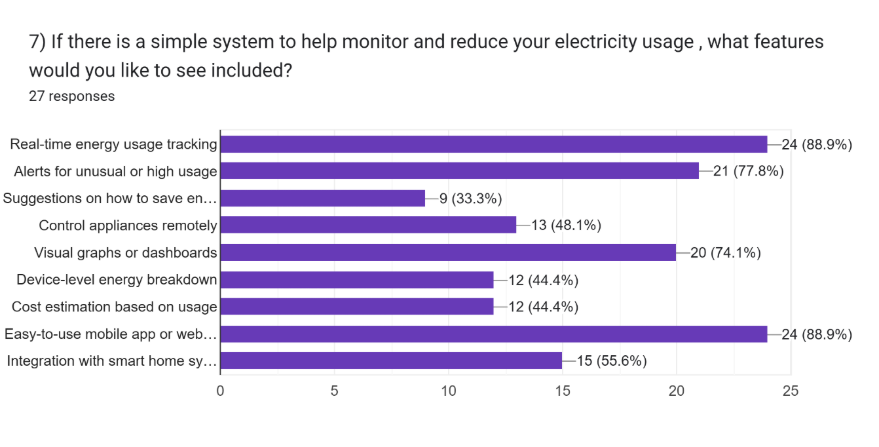
First, we did a simple survey to see what challenges people faced in saving electricity, and the features they would want in a smart home system designed to monitor its consumption.
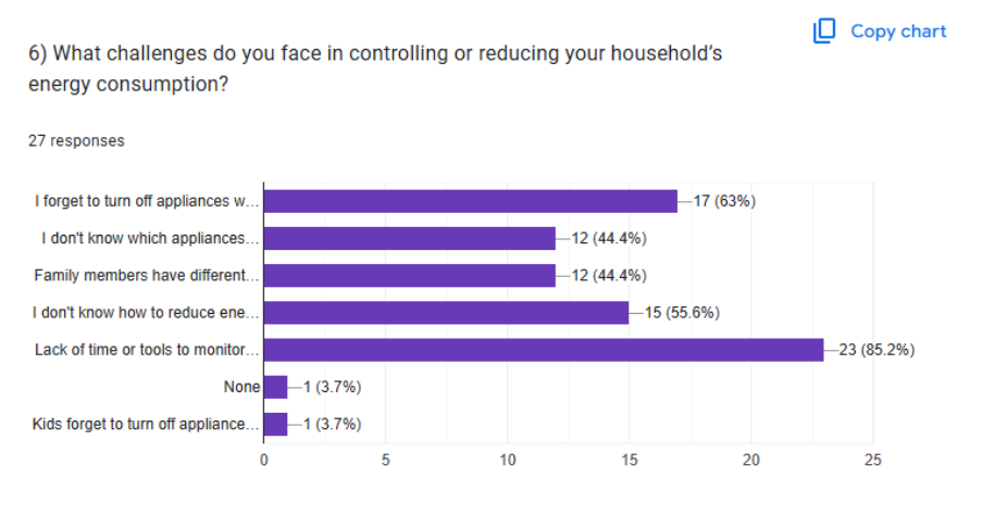
From this we found out that most of the respondents have forgotten to turn off devices not in use and lack the ability to monitor the usage of electricity conveniently and efficiently.
Designing the Solution
From the survey results, we decided to have real-time electricity consumption monitoring added to our smart home system. Then, we added some more features we thought were useful in demonstrating the connected system, like a fire detection system, a light controller system, and a door knock detection system.
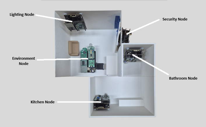
This diagram shows a mockup of a house, and where what node is supposed to be installed at. There are 5 nodes in total.
- The Lighting node controls the light
- Environment node controls and measures the room climate's conditions using fans and the air conditioner
- The Security node houses the door knock detection system and an alarm
- The Kitchen node contains a device to monitor the fridge's energy consumption and a fire detection system
- The Bathroom node contains a device to monitor the water heater's energy consumption and also has a timer to track shower duration.
Kitchen Node
For this project, I was in charge of building and coding the Kitchen Node. This node consists of 4 MIKROE clickboards.
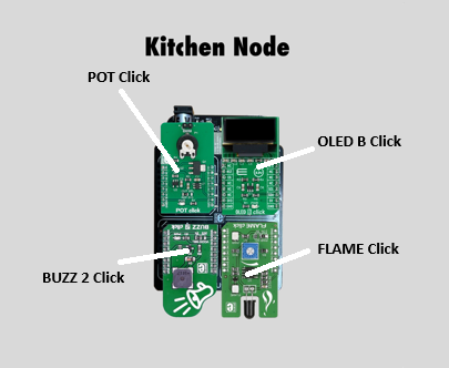
The BUZZ 2 Click, a magnetic buzzer, works in tandem with the FLAME CLick, that detects infrared light emitted by fires. When the FLAME Click detects infrared light, the buzzer will sound an alarm, and also send a notification to the dashboard.
The OLED B Click and POT Click are to emulate an electricity meter. The POT Click, a potentiometer, has its voltage read by the device, and also sent to the dashboard. The OLED B Click also shows the voltage on its display.
The Dashboard
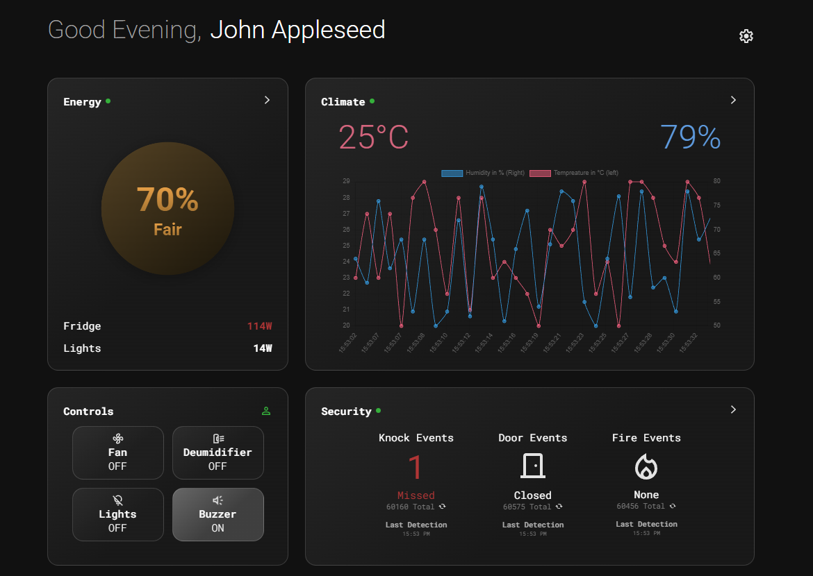
This dashboard website was built by one of my teammates, and hosted on his server for this project. For a closer view, click here! This dashboard shows all the current statistics of the house, like temperature, energy usage, and alerts like door knocks and fires detected. There is also a small section to control appliances linked to the connected system. Below the dashboard is also an interactive 3D view of a mock up house in which our smart home system is installed in, that shows real-time status of appliances in the house, like the front door being open, or the lights being turned on.
For sending data from the nodes to the dashboard, we used a python script that emits SocketIO events that can be listened to by both sides, allowing for data to be transmitted.
What I learnt from this project
- Microcontroller pins, and programming of a microcontroller
- Knowledge and application of the engineering design process, and thought processes to derive ideas.
- Simple linux command line knowledge, like connecting to WIFI and navigating file libraries
Conclusion
Through this project, I really learnt how simple microcontrollers are. Though learning the javascript needed to allow the dashboard to transmit and receive data, and coming up with ideas of a connected system to satisfy the project requirements, were otherwise.